Understanding Plant 3D Piping Design
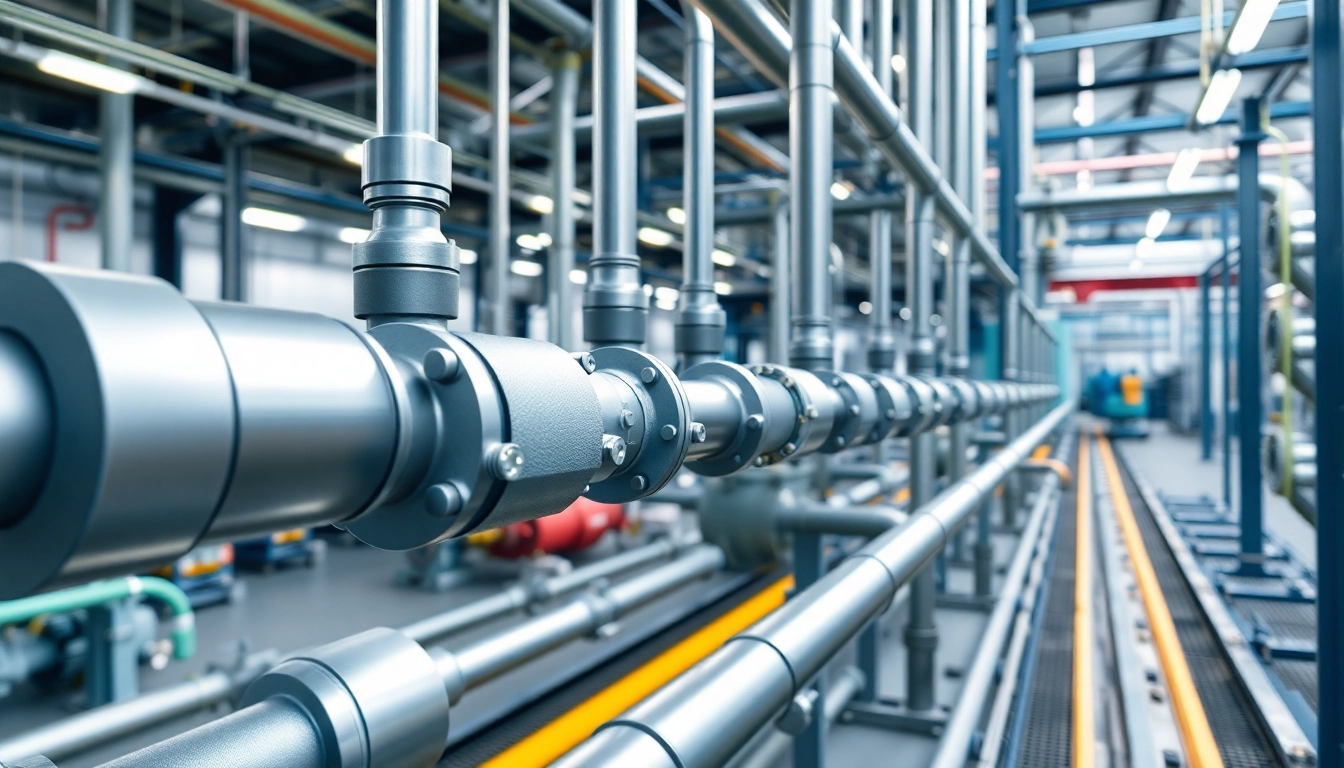
Plant 3D piping design is a crucial element in the field of engineering and construction, focusing on the creation of intricate piping systems for industrial plants. Utilizing advanced software tools, engineers and designers can create detailed 3D models that improve both the efficiency and accuracy of piping projects. With the increasing demands for precise and optimized design solutions, mastering Plant 3D piping design has become essential for professionals in this field.
What is Plant 3D Piping Design?
Plant 3D piping design refers to the process of designing, modeling, and detailing piping systems within a 3D environment. This approach allows engineers to visualize their projects accurately and address potential design conflicts before physical implementation. The key aspects of Plant 3D piping design include the use of intelligent 3D models, which contain all necessary data regarding pipe materials, sizes, and specifications.
Key Benefits of Using Plant 3D
The benefits of implementing Plant 3D piping design in your projects are numerous:
- Enhanced Visualization: Users can create realistic 3D models which provide a better understanding of the project.
- Improved Collaboration: Team members can work on the same model, reducing miscommunication and errors.
- Better Efficiency: Intelligent features automate routine tasks, speeding up the design process.
- High Accuracy: The accuracy in drafting reduces costly mistakes during construction.
- Compliance: Built-in features ensure that designs adhere to regulatory standards.
Fundamental Components of Plant 3D Systems
Understanding the essential components of Plant 3D systems is crucial for effective design:
- Piping Components: Includes pipes, fittings, flanges, valves, and supports.
- Equipment: Tanks, vessels, and reactors that interact with the piping systems.
- Isometric Drawings: Used for extracting fabrication-ready documentation.
- P&IDs: Process and Instrumentation Diagrams which showcase the design intent and functionality.
Getting Started with Plant 3D Piping Design
Installing and Setting Up Plant 3D
The first step in using Plant 3D piping design software involves installation and setup. Follow these steps to ensure a smooth installation:
- Ensure your system meets the required specifications for the software.
- Download the installation package from the official website.
- Run the installer and follow the on-screen prompts to complete the installation.
- Activate the software using the provided license information.
- Configure initial settings according to your project requirements.
Navigating the User Interface
Once installed, understanding the Plant 3D user interface is crucial. The interface typically includes:
- Main Toolbar: Contains frequently used commands and tools.
- Project Browser: Allows users to manage different models and assemblies.
- Drawing Area: Where the actual modeling takes place.
- Properties Panel: Displays the details and attributes of selected components.
Creating Your First Piping Model
Starting your first piping model may seem daunting. Here's how you can do it effectively:
- Begin a new project from the start menu.
- Select the appropriate template for piping systems.
- Utilize the toolset to place piping components in the drawing area.
- Connect the components using the routing tools available.
- Save regularly to ensure you do not lose your progress.
Advanced Techniques in Plant 3D Piping Design
Configuring Pipe Layouts Effectively
Configuring efficient pipe layouts involves strategic planning and execution. Consider the following:
- Routing Preferences: Define your routing preferences based on project requirements.
- Utilizing Hierarchy: Use different layers to organize piping systems logically.
- Automated Routing: Leverage the software's automated routing capabilities to save time.
Integrating Equipment and Fittings
Successful integration of equipment and fittings can significantly enhance functionality:
- Select equipment models from the library and place them appropriately in your design.
- Ensure proper alignment with the piping systems.
- Modify fitting specifications as per project requirements.
- Utilize the clash detection feature to identify conflicts.
Performing Isometric Drawings
Creating isometric drawings is essential for real-world fabrication:
- Access the isometric drawing tool within the software.
- Select the piping components to be included in the drawing.
- Customize the drawing settings to fit fabrication standards.
- Export the finished drawing for further processing.
Common Challenges in Plant 3D Piping Design
Overcoming Piping Layout Issues
Piping layout issues can arise, but the following tips can help manage them:
- Proactive Planning: Create preliminary designs to anticipate complex routing.
- Utilize Feedback: Regularly review designs with peers for input.
- Software Training: Ensure all team members are proficient with Plant 3D features.
Dealing with Software Limitations
Using the software effectively can sometimes present challenges. Consider these strategies:
- Regular Updates: Keep your software updated to benefit from the latest features.
- Training Resources: Utilize available tutorials and documentation to enhance knowledge.
- Active Community: Engage with online forums and communities for troubleshooting advice.
Ensuring Compliance with Standards
Adhering to industry standards is paramount:
- Understand Regulations: Familiarize yourself with relevant industry standards and codes.
- Automation Features: Use compliance-checking features to ensure adherence during the design phase.
- Documentation: Maintain thorough documentation of all design decisions for audits.
Evaluating Your Plant 3D Design Outcomes
Measuring Efficiency of Piping Design
To evaluate the success of your piping design, consider the following metrics:
- Time to Completion: Measure the time taken from the design phase to implementation.
- Budget Adherence: Evaluate whether the project stayed within budget estimates.
- Error Rate: Track the number of design errors encountered during implementation.
Utilizing Feedback for Improvement
Feedback is essential for continuous improvement:
- Gather input from project teams regarding the design process.
- Analyze feedback to identify common areas for improvement.
- Implement training sessions to address skill gaps identified in the feedback.
- Keep an open line of communication for ongoing input during future projects.
Future Trends in Plant 3D Design
The future of Plant 3D piping design includes exciting advancements, such as:
- AI Integration: Artificial intelligence will streamline design processes and automate routine tasks.
- Cloud-Based Solutions: Enhanced collaboration through cloud-based design platforms will become standard.
- Enhanced Virtual Reality: Utilizing VR will allow for immersive design reviews and client presentations.
FAQs about Plant 3D Piping Design
1. What software is essential for Plant 3D piping design?
Autodesk’s Plant 3D is the primary software necessary for creating and managing piping designs effectively.
2. Can I use Plant 3D for different industries?
Yes, Plant 3D is versatile and applicable in various sectors, including oil and gas, pharmaceuticals, and food processing.
3. Is training available for learning Plant 3D?
Numerous online tutorials, courses, and workshops are available for beginners and experienced users alike.
4. How does Plant 3D enhance collaboration?
The software allows multiple users to work on a single model, making real-time collaboration effective and reducing errors.
5. What are isometric drawings in Plant 3D?
Isometric drawings are 2D representations of piping systems that reflect three-dimensional objects at a 30-degree angle.